Introduction to Municipal Solid Waste Incineration
Marjorie J. Clarke, Scientist in Residence
Lehman College, Geography Dept.
Bronx, NY
Air and Waste Management Association Annual Meeting
Baltimore, MD
June 23-27, 2002
Abstract
The solid waste management hierarchy, adopted as U.S. national policy in 1988, is reinforcing the focus away from landfilling and towards waste prevention, recycling, composting, and Energy-from-Waste in that order of priority. Incineration of municipal solid waste evolved from a means of reducing the volume of waste via uncontrolled burning to a sophisticated technology with improved designs for combusting the waste stream, extracting heat for steam and electricity generation, monitoring and controlling emissions, and carefully handling ash. This brief overview describes the process of incineration, the products of complete and incomplete combustion of waste, pollution prevention, emissions control, and ash management.
(Note: Footnotes were lost upon conversion to html.) References are available at the end.
Introduction
The solid waste management hierarchy, adopted as U.S. national policy in 1988, is reinforcing the focus away from landfilling and towards waste prevention, recycling, composting, and Energy-from-Waste in that order of priority. This hierarchy prioritizes waste prevention and waste management techniques like reuse, recycling, and composting as superior to both the incineration/ash management alternative and to landfilling for a number of reasons. These include economics, energy efficiency, and environmental soundness, evaluated from the standpoint of lifecycle assessment (i.e., total cradle-to-grave impacts including mining, manufacturing, transportation, use/reuse, and disposal). For example, reducing the use of office paper by using a double-sided copier (source reduction) is superior to copying on one side of the paper and sending more paper off to undergo processing, remanufacture, repackaging and redistribution (recycling). Both of these alternatives are better than burning the paper (incineration) and landfilling the ashes, or simply landfilling the paper itself, since these processes result in the forfeit of great savings in energy, materials, and environmental resources to be had either by recycling the paper into new paper, instead of manufacturing paper from virgin resources, or by reducing the amount of paper used, conserving natural resources.
Incineration and landfilling most certainly result in greater lifecycle environmental impacts than recycling or prevention, hence their lower priority in the hierarchy. For example, incineration results in air emissions and ash, which is sometimes toxic, both of which require management. Landfilling creates emissions of greenhouse gases, such as CO2 and methane, as well as other toxic organic gases and leachate (i.e., rainwater contaminated with metals, chlorides, sulfates, and organics). Though landfills in the U.S. are now starting to be constructed to minimize leaks of leachate (i.e., including multiple liners, leak detection systems, and leachate collection and treatment systems onsite), and to minimize emissions (i.e., with onsite landfill gas collection and treatment systems), these systems are costly, and are not perfect. Leaks can still happen over time, and gas collection within large landfills does not prevent escape of all gases produced there. And, of course, landfilling does take up space which is not always easily reclaimed for other purposes. Just recently, an increased incidence of cancer in the faculty and staff of a school built over a closed landfill in New York City caused suspicion that the two were linked.
The advent of the solid waste hierarchy occurred almost contemporaneously with the transition from the old-style incinerators (i.e., those that did not recover energy, and do not have advanced emission control systems) to waste-to-energy (WTE) plants, as they are called in the U.S. Also at this time the public began to recognize an increasing severity of environmental deterioration as global and local phenomena, engendering a rising public outrage against incinerators and a call for increased prevention, recycling, and composting. After many WTE plants were built in the late 1980s and early 1990s, some waste-to-energy plant plans in the U.S. were scrapped because of objections over emissions; others have been scaled down in size because of the success in recycling programs, which left less waste for the WTE plants. Still other plants, which were designed for 100% or more of a locality's waste stream, have gone begging for nearby communities’ waste when their recycling programs "took off", in order to receive enough tip fees to satisfy facility debt requirements. Table 1 shows the distribution of WTE facilities as of 1997.
Despite the fact that the hierarchy prioritizes waste prevention, recycling, and composting as preferable waste management techniques, in the short-term incineration with energy recovery is likely to be a component of integrated municipal solid waste (MSW) management systems in many localities (particularly those without access to inexpensively priced landfills) due to the fact that the preferred methods have not achieved the capacity to prevent and process anywhere near 100% of the MSW in any locality. An extensive 46-material sort waste composition study done for New York City in 1990 showed that 80% of that city’s waste stream was recyclable or compostable and some was reusable or repairable. But to date, relatively few municipalities in the U.S. have achieved as much as 50% materials separation and reuse (e.g. a number of cities in California, Minneapolis, MN, Newark, NJ).
One challenge for localities developing integrated solid waste management systems in the future will be to ensure that all types of facilities designed to process and treat solid wastes are sized appropriately. In order to size and burn waste in the incinerators of the future, research will be needed to provide better estimates of the quantity and quality (BTU content, toxic precursor content) of municipal solid waste (MSW) that will be prevented, recycled, and composted, and thus, the characteristics of the waste stream remaining for incineration. Though the characteristics of MSW will necessarily fall in a range, such information will be valuable in designing optimally-sized plants as well as designing emission control devices appropriate for the incoming waste stream. (The same goes for sizing recycling and composting facilities; the amount and type of waste prevention which may be achieved in the future should be considered in sizing incinerators.)
Table 1. Municipal waste combustors, 1997.
Another challenge facing municipal officials regarding integrated planning will be to quantify and factor into their decision-making all facets of environmental impact expected to be generated by each management alternative (e.g., trucking, emissions, effluents, solid wastes, avoided environmental impact). Siting is a particularly difficult issue in densely populated urban areas, yet these are the ones more likely to consider incineration. There is a history of NIMBY (not in my back yard) protests by residents of areas slated for siting of a plant. Consequently, localities would do well to choose solid waste management technologies that minimize environmental impacts to the fullest extent -- even more aggressively than the law requires (especially since current law typically lags well behind the State-of-the-Art). Designing instantaneous emissions reporting systems that display results on the internet can also be reassuring. Municipalities would also be well advised to design their solid waste management programs to be as flexible as possible. Finally, in the future, municipalities which successfully implement integrated solid waste management programs will discover that an important factor in their success is the result of working in full cooperation with environmental and community groups, utilizing mechanisms known variously as Citizens Advisory Committees (CAC's) and Solid Waste Advisory Boards. In fact, embracing all these approaches simultaneously will foster and hasten the development of generally accepted integrated solid waste management systems.
What does all this mean for the role of solid waste incineration in future integrated waste management plans generally? Though a number of municipalities have relatively new incinerators to dispose of at least some solid waste as part of integrated solid waste management systems, there are others whose landfills may be filling up and which might want to consider an incinerator. In the longer term, Congress may ban or limit interstate transportation of solid waste to landfills (this has been considered for years), and as older, cheaper landfills close, new ones designed to modern standards become more expensive. On the other hand, there is still great potential for waste prevention, recycling and composting programs to divert more of the waste stream, both by targeting more materials and by improving education programs. Thus, the future of incineration is uncertain.
Given the realities of a future with a large variety of local integrated waste management systems, the composition of the incoming waste stream for incinerators can easily change from that of the present, with further consequences on the design of waste-to-energy plants and the quantity and quality of emissions and ash produced by them. If mainly noncombustibles and lesser combustibles such as glass, metals, and yard wastes are diverted for recycling, the BTU content of the waste remaining to be burned would rise considerably necessitating a furnace with larger volume for combustion. If the City of New York persists in its desire to stop collecting source-separated metal, glass, and plastic, the waste brought to two nearby incinerators will, adding more non-burning, ash-producing materials to the feedstock. If, on the other hand, a large percentage of paper and plastics are targeted for source-separation, the boiler design would need to reflect this also. So waste composition must be characterized and taken into account during the design for a new or retrofitted plant in order to be certain of throughput capacity, emissions, energy generation and ash production, and therefore the tip fees and the economic viability of the plant.
These plants will be developed according to increasingly stringent design and operating standards to minimize emissions. As superior methods of operation are devised, based on experience with the population of existing incinerators, such changes will be introduced over time. Periodically, as important new technologies are developed for stabilizing combustion or minimizing emissions, major retrofits will be required. Improvements in monitoring of all emissions of concern, and in accurate and instantaneous reporting of these data to the environmental regulatory authorities, will continue.
Incinerator Design
Incinerators were originally designed solely for the purpose of reducing the volume of MSW left for disposal. An ancillary purpose was to accomplish this reduction of volume in an efficient and sanitary manner (that is, to destroy breeding places and propagating causes of vermin and disease). In the past, before the advent of recycling and waste prevention, which has modified the waste stream, incinerators were fed a heterogeneous mix of unprocessed or raw garbage, trash, and other wastes from different sources (e.g., medical wastes). The combustion itself was unregulated, for the most part, in terms of temperature and oxygen control, and consequently, the waste was often not completely burned to carbon dioxide, water vapor and ash, and there were considerable emissions of air pollutants.
Since the early days of municipal incineration, plant design has evolved considerably to include more complex systems for
1. waste preparation and stoking (screening, processing, and feeding into the incinerator)
2. waste incineration and emissions mitigation via efficient combustion
3. energy extraction
4. emissions mitigation via neutralization and/or capture in control devices
5. ash handling
The following table illustrates the components of solid waste incinerator systems: (1) inputs, (2) preparation, (3) incineration, (4) emissions controls, and (5) outputs, and can be visualized schematically in Figure 1.
Each of these major steps is critical to the design and operation of a waste-to-energy system to maximize environmental performance. Figure 2 shows a schematic of an actual waste-to-energy plant. Note that there are a variety of possible configurations.
Inputs
In addition to the municipal solid waste (MSW) itself, inputs into the waste-to-energy process include fossil fuels, which are used to keep the furnace hot when starting up, shutting down, or during upsets, to reduce the creation and emission of organic compounds. Water, consumed in emission control devices called scrubbers, cools and removes pollutants from combustion gases. Reagents, such as lime and activated carbon, are injected into the flue gas, using control devices to reduce emissions.
Figure 1. Incineration Schematic
Figure 2. Schematic diagram of Commerce, CA incinerator
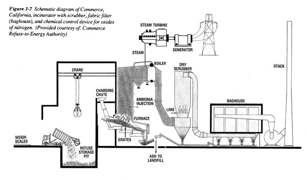
Source: Clarke, Marjorie J., et. al, Burning Garbage in the US: Practice vs. State of the Art, INFORM, New York, NY. 1991.
Waste Preparation
Before the incineration process, the MSW undergoes a number of preparation steps. The first can happen outside the WTE plant and/or in an adjacent part of the plant: separation of recyclable and compostable materials, separation of reusable products, and reduction in generation of products in the waste stream due to source reduction. This step reduces both the volume and typically alters the composition of the waste, which can affect the quality of combustion and the quantity and toxicity of emissions and ash produced.
Since it is important to minimize the entry of hazardous, flammable, explosive, and toxic materials and other items not suitable for incineration, MSW incinerators should also be designed and operated to maximize the opportunity for inspection and screening out of undesirable wastes. Two consequences of not removing unsuitable items include (1) explosions in the furnace of flammable/explosive materials and (2) contribution of concentrations of pollutant precursors, such as heavy metals (in batteries, appliances, and automotive parts), chlorine (in PVC and bleached paper), and organics (in solvents) resulting in higher emissions.
Adequate screening is best accomplished by designing the screening area so that waste can be closely inspected, rejected, and removed if the need arises, before it is fed into the furnace. Two designs are currently in general use for this purpose; only one permits visual screening. At the larger plants, trucks dump their loads directly into sizable pits below grade; this prohibits screening. At smaller plants tipping floors are typically used. In this design trucks dump their loads onto the floor in a large room in which wastes can be spread out and inspected. If inappropriate wastes are spotted, the plant management can order the truck that dumped the offending load to remove it.
In addition to routine screening for unacceptable items in the waste stream, at some incineration plants further preparation and/or pretreatment of the wastes takes place prior to incineration. Because mass burn plants are designed to burn unprocessed solid waste, hence the name mass burn, the waste processing stage is minimal, and involves only mixing and drying of wastes. This takes place above the pit as a crane operator captures as much as a ton of waste at a time in the jaws of the grapple and moves it within the pit and to the waste charging chute leading to the furnace.
Though the style most often used has been mass burn, there are quite a few refuse derived fuel (RDF) plants in use. These facilities are distinguished from mass burn plants by the presence in the plant design of waste pre-processing equipment. Refuse derived fuel is the name given both to the residual end product created by the processing and to the plant which burns the material. In RDF plants the truck usually dumps unprocessed MSW onto a conveyor which leads into a facility separate from the incinerator for preprocessing and sorting into resource streams. Though RDF plant designs differ according to the types of resources recovered and the degree of resource purity achieved in the end product, RDF is generally derived by removing noncombustible metals, glass and grit, and subsequently processing the remaining combustible waste to a uniform size. The RDF is a highly combustible and versatile feedstock containing mainly paper and plastic, which can be burned either as-is (a fluffy material) or in a dense, easily transported pelletized form. It can be burned either alone in a dedicated furnace/boiler attached to the processing facility (as most RDF plants are configured) or commingled with another fuel (e.g. sewage sludge, wood, coal) and shipped in pellet form off-site to another facility.
Once the undesirable components of the waste stream have been removed, the waste is fed into the drying area adjacent to the furnace. The waste charging process is either done in batches (which usually causes combustion to be less stable because relatively cold outside air is introduced into the combustion chamber periodically), or continuously, by charging the waste down an inclined chute onto a moving grate. It is preferable to have the waste spread out evenly to maximize combustion, so grate systems are designed to have speed adjustments. The grate is sped up when highly combustible waste is fed, and slowed down when waste is wet or lower BTU-value.
Maximizing Combustion Efficiency
As is shown in Figure 1, there are a number of alternative combustor designs used to burn garbage. In most mass burn plants the grate system moves the solid waste through the drying, burning, and burnout zones, while promoting combustion. This is done by ensuring that adequate (but not excessive) quantities of air enter from below via holes in the grates. Complete combustion optimally involves a two-stage transformation of fuel, in this case solid waste, into CO2 and water vapor. It is important to note that emissions of these two compounds contribute to global warming.
In the drying stage as solid waste is fed onto the grate system, it encounters the high temperatures of the furnace, the box in which the heat and combustion gases are contained. At this stage the burning solid waste gives off volatile gases (e.g., mercury and volatile organic compounds). The MSW is heated and dried, and then eventually ignites.
The secondary phase of incineration (combustion) takes place as the combustible materials (e.g., paper, plastics, organic materials containing carbon, hydrogen and oxygen) combine with oxygen to form carbon dioxide and water vapor (oxidizes). But in incinerators, since the waste stream is so heterogeneous, other compounds are also formed and buoyed upward off the grate by the heat of combustion. There are unburned carbon particles, incompletely burned carbon-based compounds (e.g. organic products of incomplete combustion (PICs) such as carbon monoxide, PAH's, and the more toxic dioxins and furans often referred to as "products of incomplete combustion, or PICs), and incombustible elements such as heavy metals, sulfur, nitrogen, and chlorine, which combine with oxygen and hydrogen in the furnace to form compounds such as HCl, SO2 and oxidized metals.
It is also at this location in the furnace where the critical temperatures must be attained for proper combustion. The efficiency of the combustion process, and therefore incineration, is characterized by the "three T's": temperature, time, and turbulence. To achieve the temperature requirement, an adequately high and uniform temperature profile must be maintained throughout the furnace volume at all times in order to destroy PICs reliably. In order to optimize combustion of these gases, it is generally considered that the temperature profile (or the secondary chamber) should not fall outside the range of about 1800-2000oF. This means that the temperature should be uniform with no cool spots or short cuts for the gases to exit. Cool spots can occur adjacent to the furnace's walls, since it is here where heat is first extracted from the combustion process. The furnace's "waterwalls" consist of banks of steel tubes which contain boiler water circulated from the boiler, which is then heated by the high temperatures in the furnace, and is subsequently returned to the boiler. Minimization of cool spots is achieved by increasing the time and turbulence factors.
Considering the heterogeneous nature of municipal solid waste, with some components highly combustible and others not, strict maintenance of at least a minimum temperature throughout the furnace is necessary. In modern incinerators maintenance of temperature is aided by means of auxiliary burners. These devices are fed fossil fuels and are typically set to come on automatically when the furnace temperature falls below a predetermined threshold. This temperature is usually between 1500 and 1800oF at the location of the auxiliary burner (several feet above the grates where the highest temperatures are attained).
To achieve the time criterion, the gases produced in the combustion process must remain in the high temperature zone of the furnace for at least a minimum residence time, usually at least the one to two seconds required to destroy most gaseous organic compounds. Achieving this much residence time is usually accomplished by means of designing the furnace to retard the rate at which gases flow through it, usually by installing into the furnace walls irregularities or other features which cause the combustion gases to flow in a turbulent fashion.
Turbulence actually refers to adequate mixing of the proper ratio of combustion gases with oxygen. In order to maximize the turbulence factor, there must be sufficient oxygen present in the furnace in order for the organic matter in solid waste to be burned completely. Both residence time and turbulence or mixing are maximized by designing the furnace so that the proper amount of air is introduced at the appropriate locations. Turbulence is also aided by optimizing the direction of the secondary air jets. The air used for injection may either be fresh, from the outside, or recirculated utilizing combustion gases from a location downstream from the furnace. The latter is usually done to minimize creation of oxides of nitrogen. Optimal conditions are maintained by providing sufficient, but not excessive, air via proper design and operation of underfire (primary) and overfire (secondary) air injection. In typical mass burn incinerators for example, air injected below the grate enhances drying and primary combustion of the waste. Air injected above the grate assists in secondary combustion of gaseous volatilized organic compounds and PICs released by waste burning on the grate.
In more advanced systems, primary air is injected into the drying, burning and burnout zones separately from secondary air. Some incinerators have nine separate primary air injection ports. The control of air injection is done either via manual adjustments to dampers or automatic combustion controls. The latter is a more advanced system that senses, via continuous monitoring devices, the temperature and oxygen needs of the furnace, and then adjusts the quantity of primary and secondary air entering the furnace accordingly. In most of these advanced systems each of the three primary air zones is subdivided into a number of sections, each of which can be individually controlled. This type of system is designed to optimize the placement, velocity, and flow of air to all parts of the grate area, and improve combustion and reduce particulate generation.
Modern plants are also configured to achieve improved combustion efficiency by utilizing highly engineered designs which include arches and bull noses. Arches are located above the burning and burnout zones to contain and funnel the combustion gases into the furnace proper. Bull noses are built into the furnace walls, usually near the point of injection of overfire air, several feet above the grate for the purpose of introducing turbulence and retarding movement of the combustion gases out of the furnace. These features were designed for the purpose of guiding the combustion gases through a more circuitous path which also, not incidentally, allows the gases greater opportunity to mix with oxygen and permits them a longer "residence time" in the high temperature region of the furnace. A superior design includes careful placement of these features in such a way that semi-permanent eddy currents are established.
Continuous Environmental Monitoring
Continuous monitors of emissions and process parameters are called CEMs and CPMs. These devices have been developed over the years to assist plant operators in monitoring the process parameters that indicate the efficiency of combustion as well as the emissions of various pollutants. Careful maintenance and scrutiny of these instruments can show if action is necessary to signal the operators to change equipment settings or repair or maintain devices. Some of the CPM's and CEM's considered to be State-of-the-Art include: furnace temperature, flue gas temperature at the air pollution controls, oxygen, carbon dioxide, steam pressure, steam flow, flue gas flow rate, carbon monoxide, SO2, HCl, NOx, and opacity (a crude measure for particulate matter). In addition to these, more precise continuous emission monitors for particulate matter are in use in Europe, and continuous mercury monitors are required in some parts of Germany.
These continuous monitors are commonly used to track the environmental performance of incinerators so that in the event of combustion irregularities (upsets) or high emissions of one or more pollutants, corrective measures can be implemented in a timely fashion. For example, the four process parameters (CO, O2, CO2, and furnace temperature) though measures of combustion efficiency, are generally used as surrogates for direct measurement of PICs. This is necessary because no direct continuous monitors have yet been invented to measure certain complex PICs, such as dioxin/furan and their precursors, polycyclic aromatic hydrocarbons (PAHs), and others, though research in this area continues. The only means of determining the level of these pollutants is stack tests, which are time-consuming, cost tens to hundreds of thousands of dollars, and can consume months in sampling and analysis. Such tests cannot be used to pinpoint high emissions of metals or complex chlorinated organic compounds in time to correct the immediate cause of an upset condition, and are hence only useful for assessing the general capability of an incinerator design for achieving desired emission limits. Thus, measurement of dioxin and furan are typically undertaken only for periodic compliance tests.
Outputs
As is evident in the process schematic, outputs consist primarily of energy, emissions, and ash. As garbage is burned on the grates, the unburned solid waste is transformed into bottom ash or char which is deposited in a water bath. Some WTE plants extract ferrous metals from the bottom ash using large magnets. The energy extracted from the system is initially in the form of hot gases. The heat is transferred to the boiler, superheated steam is created, and then it can either be used as is, in a district steam loop, or converted to electricity and relayed onto the grid.
Stack Emissions
Air pollutant emissions from the stacks of waste-to-energy plants fall into five categories:
1. Particulate matter (including a number of heavy metals, such as lead and cadmium),
2. Acid gases (which include HCl, SOx, H2SO4 and HF), which contribute to acid rain,
3. Mercury, which is now a global contaminant,
4. Products of incomplete combustion, including carbon monoxide, and such toxic organic compounds as dioxins and furans and their precursors chlorobenzenes and chlorophenols), and
5. Oxides of Nitrogen (NO2, NO), usually referred to as NOx, which contribute to acid rain and ozone.
Though in some cases more than one cause can contribute to the formation of individual pollutants, emissions from incineration of municipal solid waste are usually due to trace contaminants in the waste stream and/or poor efficiency of combustion. Both of these causes suggest imperfections in the incineration process (i.e., imperfect fuel and imperfect burning). As is the case with any combustion source, incinerators operate best when they convert relatively clean organic fuel to carbon dioxide and water vapor.
Many of the most problematic emissions from incinerators are caused by such pollutant precursors in the waste as chlorine, sulfur, heavy metals, organics, and nitrogen, all of which are normally present in MSW in varying quantities. In the normal process of combustion these substances can combine with other products of combustion to produce such pollutants as HCl, SOx, H2SO4, NOx, various metal chlorides, oxides, and other compounds, and chlorinated and unchlorinated organics. If reduction of the initial waste stream contaminants or precursors could be achieved, then some reduction of emissions produced through this route might also be obtained. Unfortunately, because MSW is so characteristically heterogeneous, a single precursor, for example, chlorine, can have a number of diverse sources including PVC plastics, bleached paper products, and food waste (which contains salt). Fortunately, in the case of chlorine, substitutes are often available which use little or no chlorine. In the case of certain heavy metals the sources are also diverse, and new technologies are under development now to minimize the use of metals in products and packaging, and develop less toxic alternatives. In addition, recycling and household hazardous waste programs are increasingly diverting materials containing concentrated amounts of precursors (e.g., batteries, paint, pigmented plastics, etc...). Thus, emissions caused by transformation of pollutants contained in the waste stream are being substantially reduced, and the potential for further reductions is high.
The second cause of air emissions is inefficient combustion of the MSW, characterized by insufficient or excessive temperature, insufficient oxygen to complete combustion, excessive air which cools combustion, insufficient turbulence, and/or insufficient residence time of the pollutants at the proper temperature and oxygen conditions. If any of these conditions are present, products of incomplete combustion will probably be created -- the worse the conditions, the worse the level of emissions produced. Additionally, in the case of excessive primary or underfire air, particulate carryover can be a problem (i.e., fly ash can be lifted off the grates and carried along in the combustion gases).
Emission Control Devices
The emission control devices, sometimes referred to collectively as the pollution control train, are arranged in various combinations and sequences after the economizer (the last part of the boiler), and are connected by ductwork. These devices employ a number of physical and chemical techniques including absorption, adsorption, temperature reduction, condensation, neutralization, filtration, and electrostatic precipitation. To assist in these processes and increase the effectiveness of certain of the emission control devices, reagents such as water, lime, sodium hydroxide, activated carbon, sodium sulfide, ammonia, urea, and other, proprietary agents are sometimes injected or sprayed into the combustion gases. The design of these devices, and of the entire pollution control train, including such details as sizing, choice of construction materials and reagents, and positioning of devices in the train, are critical to the emissions removal efficiency. As important as design is to minimizing emissions, the quality of operation of the emission controls is also important, since the best equipment can function poorly and emit high quantities of pollutants if the operations are not ideal. Suboptimal operations can be caused by poorly trained and/or inattentive operators (i.e. operator error), faulty procedures, incorrect optimization of reagents, and equipment failure. Optimal operating techniques are discussed later.
Particulate Control Devices
To reduce emissions of solid particulate matter, including carbonaceous and metallic particles, and condensed matter such as metals, organics, and acids, several types of particulate removal devices have been used. In the 1970s electrostatic precipitators, or ESP's, became more common. In these devices the particulate are electrically charged and then pass between the surfaces of parallel plates containing an opposite charge, where they are collected. The efficiency of ESP's are evaluated by the surface area of the plates vis a vis the volume of flue gas requiring treatment. Early ESP designs featured one or two pairs of parallel plates or fields. More recent designs have three, four, and five fields for greater efficiency. The ESP plates are cleaned by rapping devices that cause the accumulated particulate to fall into a fly ash hopper, situated at the bottom of the ESP.
In the 1980s fabric filters, also known as baghouses, started to replace, or be used in tandem with, ESPs as the preferred mechanism for particulate removal, due to their improved capacity for filtering finer particles. (It is important to filter the fine particulate since these are able to penetrate more deeply into the lungs, and when coated with metal, organic, and acidic compounds pose a greater health threat.) Baghouses filter the flue gases in much the same way that a vacuum cleaner does, using a finely woven cloth and the dust cake, which accumulates on it, as the filtration media. Finer particles are entrapped in the dust cake, increasing the baghouse's efficiency. The greater the surface area of cloth to the volume of air requiring filtration, the greater the baghouse's efficiency in removing particulate matter. The two chief baghouse designs are known as pulse jet and reverse air. In a pulse jet baghouse, the particulate matter accumulates on the outside of bags in which stiffeners are used retain the shape. In this case the particulates drop off the outside of the bags when a pulse of air is forced into the bag. In reverse air baghouses, flue gases flow into the bags, and the particulates accumulate on the inside of the bags. Ash hoppers are also used in baghouses to collect fly ash.
Scrubbers and Heat Exchangers
To decrease acid gas emissions and increase condensation of metals and organics, scrubbers of various designs have been employed. A number of vendors, including NIRO, Deutsche Babcock, Flakt, Lurgi, Teller, and others manufacture a large variety of scrubber designs. Wet scrubbers, into which water is injected as the primary reagent for absorption of acid gases, have been used for decades, primarily in Europe. The mode of injection, usually via nozzles, is one of the main features that distinguish one vendor's scrubber from another. Wet scrubbers can discharge a wet, salty effluent which contains the acids, organics, metals, and other pollutants impacted by the water droplets in the scrubber, although newer designs in Europe employ techniques to precipitate out certain metallic and other fractions so that the water can be evaporated.
More recent developments are wet-dry or spray dry absorbers (SDA), in which both water and an alkaline reagent, such as lime, are injected as a slurry for absorption and neutralization. The names, wet-dry or semi-dry, are derived from the fact that the reagent enters the scrubber in wet (slurry) form, and exits as a dry residue, with the water having been evaporated completely in the scrubber. In the case of one design, agglomerating agents are also injected, but from a separate storage silo. (Agglomerating agents, such as Tesisorb, used in the Teller/Research Cottrell scrubber technology, facilitate the clumping together of smaller particles into larger particles. This is desirable since larger particles are easier for particulate control devices, positioned downstream in the pollution control train, to remove from the flue gases.) Dry injection scrubbers, which employ an alkaline reagent without water, have also been utilized in recent years. These scrubbers are not typically as efficient as wet or SDA scrubbers, as they are operated at higher temperatures. They also produce a dry salty residue containing a combination of alkaline and acidic agents.
In addition to scrubbers, direct and indirect heat exchangers have been used to reduce the temperature of acid gases, metals and organics, aiding in condensation. Direct heat exchangers, or humidifiers, reduce the temperature of the gases via fine water droplets. Indirect heat exchangers reduce flue gas temperature by means of an intermediate substance that absorbs heat from the gas stream. Such absorbed heat is sometimes imparted back to the flue gases as they leave the system to increase buoyancy in the stack, reducing ambient impacts.
Wet scrubber technology has dominated in European installations, and is becoming more efficient with the development of two-stage scrubbing with separate chambers targeted at different acid gases. Spray dry scrubbers have dominated U.S.-based installations with a fewer number of dry injection scrubbers. Heat exchangers have been used in Europe, particularly in Sweden, and in a few installations in the U.S.
Ash and Ash Management
Ash residue is produced as a result of incomplete combustion of a heterogeneous, imperfect fuel containing non-combustible items (municipal solid waste). There are two types of ash produced by incinerators: bottom ash and fly ash. Solid waste that is not completely burned on the grate is called bottom ash. Solid and condensable particulate matter which leaves the furnace suspended in the combustion gases and which is subsequently collected in emission control devices, is called fly ash. The unburned materials contained in bottom ash include a heterogeneous mixture of unburned organic material, or char, large pieces of metal, glass, and ceramics. Fly ash consists of a more homogeneous mixture of fine ash particles that were carried out of the combustion chamber, composed of metals, organics, and acids condensed onto the surfaces of the ash particles. Since fly ash characteristically contains more toxic pollutants than bottom ash, it is usually managed separately as a special waste in many European countries.
Two concerns of ash management on-site are the safety of the workers and the possibility of fugitive ash escaping into the environment during handling or removal of the ash for disposal. Both concerns require that the ash be contained at all times both inside and outside the plant. In the plant, water is used to quench the ash, minimizing the spread of ash dust that is so easily inhaled or ingested by the workers. A closed system of conveyors which transports the ash from the furnace to the trucks also helps to minimize exposure to the workers. While some facilities have partially closed ash removal systems, few facilities have a completely enclosed system for transporting ash through the plant.
Ash containment off site is best achieved through the use of covered, leakproof trucks for ash transport, to prevent ash from escaping into the environment through wind dispersal or leaching of the quench water. Better yet, it is advantageous to manage ash at the facility if proper management is possible, so that it never leaves the premises. The most common method of ash management is disposal in landfill, either commingled with MSW or alone in an ash monofill. Here, ash must be wetted down frequently to avoid dispersal. Other methods of ash management involve reuse, either in construction materials (e.g. bricks), roadbeds, or in experimental reefs. The long-term environmental effects of these practices have not been determined.
The Role of Pollutant Precursors in the Waste Stream and Emissions From Incinerators
Waste Composition
The characteristics of wastes fed to an incinerator have a significant effect on the quality of combustion and energy recovery, the longevity of waste handling equipment inside the plant, such as the grates and boiler equipment, the quantity and characteristics of emissions, and the quantity and toxicity of ash produced. Solid waste characterization studies have been designed to produce information helpful to the optimal design and operation of incinerators. For example, the characteristic which determines how well the solid waste burns in an incinerator is the BTU value (ancillary parameters are higher heating value and moisture content). BTU value expresses the quantity of heat produced per pound of solid waste and is the chief determinant of the rate at which solid waste can be burned. This is referred to as throughput or rated capacity of the incinerator. Thus, a higher BTU value will result in a greater amount of energy recovered per ton of waste burned than a lower BTU value.
Another characteristic of solid waste is its abrasiveness. Over time certain constituents of solid waste, such as glass and tin cans, can cause considerable wear and tear on the waste handling portions of an incinerator.
One of the major properties of solid waste affecting emissions and ash is the pollutant precursor content. Pollutant precursors are elements or compounds which, when burned in an incinerator, can result in unwanted emissions or contaminated ash. Some of the pollutant precursors of interest in incineration are chlorine, sulfur, nitrogen, and fluorine, and heavy metals such as lead, cadmium, mercury, and chromium. For example, incinerating unprocessed or raw solid waste containing heavy metals like mercury (from batteries), cadmium (from pigments in plastics), or lead (from solder and car batteries) must result in those same quantities of heavy metals in the output streams with an adverse effect on the incineration process and heat recovery since metals have no BTU value. As another example, it was found that preventing gypsum board (wallboard), which is calcium sulfate, from entering a WTE plant in Vancouver decreased by half the amount of SO2 emitted from the facility. Thus, in-depth knowledge of MSW characteristics is most important insofar as incinerator performance is concerned.
Chlorine and emissions of HCl and dioxin
In 1987 the American Society of Mechanical Engineers’ Dioxin Committee completed a test of the theory that waste composition (i.e. PVC in the waste stream) correlates with HCl and dioxin emissions. The tests, carried out at the Pittsfield, MA plant, measuring at the boiler outlet with a secondary furnace temperature of 1800oF (average of 2 tests), showed that HCl went up considerably as chlorine in the waste rose. Though the sample size was similar, the test results to correlate chlorine input and dioxin/furan output were deemed "not statistically significant" by the authors because there were only a few data points. The data did seem to indicate a linear relationship in the case of furans. In fact, PCDF appears to be directly proportional to chlorine content. Since these tests of the PVC/dioxin connection were quite limited in scope and number, more research to determine a more precise relationship between quantity of chlorine in a waste sample vs. dioxin and furan created at given combustion conditions would undoubtedly provide more useful information.
Though combustion conditions are the primary factor controlling dioxin formation and its destruction, it has been theorized that alteration of the composition of the waste stream (specifically, to limit the amount of chlorine, usually in the form of PVC plastic which contains 30 to 50% chlorine) could result in a decrease in the formation of dioxins and their precursors. Though PVC may be a major contributor of chlorine to the waste stream, there are other major sources, such as sodium chloride found in food wastes and bleached paper. Thus, the debate centers around whether separation of PVC plastics from the waste stream could reduce the quantity of chlorinated organics formed, and also on whether if in the future, chlorinated plastics, such as PVC, become more prevalent in the waste stream as trends seem to indicate they will, more chlorinated organics might be formed in solid waste incinerators. Research in this area is significant in that PVC in the packaging of food; and packaging, including mainly paper, already accounts for 30 to 50% of the waste stream by various estimates, and is growing steadily.
There is also some controversy regarding the partitioning of chlorine and other pollutant precursors in the incinerator outputs. Some researchers say that emission control devices can make up for any increases in pollutant precursors in the waste stream, and that all or most of the increase would end up in the ash. This would argue against the benefit of toxic source reduction measures to reduce pollutant precursors in MSW. However, an indication of the potential benefit of limiting the quantity of chlorine in paper and plastics entering incinerators is found in tests of hospital incinerators in California. In these tests, where the waste consisted of 90-95% paper and plastics, with clearly higher chlorine content than typical MSW, and where combustion efficiency was high, as confirmed by an average of 50 ppm CO, the total dioxin and furan emissions were nonetheless well over 1,000 ng/m3. Evidently, the presence of higher concentrations of chlorine in the waste stream (and other precursors/building blocks of dioxin/furan in the lignin of paper and in the structures of plastics) can overcome good combustion, resulting in high dioxin emissions. EPA's recent Dioxin Assessment seems to point to an association between the amount of PVC in various waste streams (MWC, medical, and hazardous waste incineration, secondary smelting, etc..) and dioxin emissions, and that MWC's are one of the largest sources of dioxin emissions. Thus, as one potential means of limiting these emissions, governments could consider banning PVC waste items from incinerators and require a phase-out of bleached paper products.
Heavy Metals
There is a global mercury problem, where accumulation in the food chain is increasing (e.g. there are fish eating advisories in 31 of the 50 states). It has been concluded by a number of scientists (speaking at the May, 1994 Northeast States for Coordinated Air Use Management and October, 1994 New Jersey Department of Environmental Protection mercury conferences) that MWC's are a large source of mercury emissions. Since the significant contribution to mercury in the waste stream by batteries is similar to the contribution of lead and cadmium as shown in the Franklin study, it would seem that battery separation might be an efficient method of removing a major source of metals from emissions. Though some researchers argue that, at least for cadmium, spiking the waste stream with this metal produces an insignificant rise in emissions, with the preponderance going into the ash. But several years ago the Swedish government instituted measures at the consumer level to reduce the emissions of mercury from MWC's including battery separation. This has been successful at reducing these emissions by 50% In addition to removing noncombustibles containing mercury, measures to limit mercury in combustibles could also serve as a control technology for mercury. Since paper and plastic are highly combustible and they contain significant quantities of the total mercury in MSW (13% and 10% respectively ), their removal from the waste stream and/or the banning of mercury in paper and plastic would ostensibly serve to lower metals emissions. In 1994 the State of New Jersey enacted regulations based in part on emissions controls and in equal part on mercury source reduction resulting from state laws reducing mercury in batteries and packaging. Thus, it appears that significant control of mercury emissions might be effected by limiting mercury entering incinerators.
Another reason to consider reducing the input of metals in the waste stream is that certain metals seem to catalyze dioxin formation. The U.S. Environmental Protection Agency has noted the work by Stieglitz and Hagenmeier which show that flue gas temperatures in the range of 392-752oF enhance the secondary formation of dioxin/furan downstream, and thus has required that the inlet temperature to the particulate control device not exceed 350oF. Along these lines, it also seems quite appropriate to require a phase-out from the waste stream of those heavy metals, including copper, cadmium, zinc, antimony, chromium, and lead, which have been demonstrated by Stieglitz and/or by Environment Canada to catalyze these secondary dioxin/furan formation reactions when present in the flue gas in trace quantities. Stieglitz pointed out that removal of waste stream items containing metals would assist in minimizing this secondary formation reaction. This data argues for inclusion as part of good combustion practice, requirements for preventing these heavy metals from entering incinerators, either by mechanical or source separation or by source reduction measures such as bans (e.g., the 1985 Swedish ban on the use of cadmium as a pigment, stabilizer or surface coating). Additionally, as a back-up measure to limit the escape of mercury and other metals, it makes sense to institute measures to limit the presence of mercury and other metals in the solid waste entering incinerators, (e.g., separation and toxic source reduction requirements).
Though recovery of energy via waste-to-energy is a noble objective, reduction, recycling, and composting save even more energy by reducing the energy required to mine, log, transport raw materials, refine, manufacture, transport manufactured products, etc... Reducing the amount of waste items which when reduced, recycled, or composted, result in preservation of a higher order quality of natural resource is justified from a lifecycle point-of-view. Particularly when the material does not burn well in a MWC, it makes sense to avoid incineration.
The law of conservation of mass indicates that what goes in comes out (in some form, anyway). Though this is a hotly contested concept these days, prudence indicates that governments should support a targeted materials separation program right away to minimize feeding MWC's items containing concentrations of pollutant precursors. Table 2 is a list of items which could be targeted for separation, the reason for this separation, and the proper management of the item in an integrated solid waste management system.
Advanced Emissions Control Designs
Dioxin and Mercury
Many advanced emission control technologies are operating, with good results, on European and/or American plants. These include: dual-stage wet scrubbers, Electro-Dynamic Venturi technology (EDV), condensers, fixed deep bed activated carbon technology, injection of combinations of reagents, such as Sorbalit, Selective Catalytic Reduction, and flue gas recirculation. All have demonstrated superior emissions control capability, primarily for removal of dioxin and mercury (the latter two reduce NOx emissions ).
Table 2. Toxic products in the waste stream and their proper management.
WP = Waste Prevention; can include legislation or other actions to limit or exclude pollutant in product, or to exclude or limit product from manufacture or disposal, or to promote substitute, less toxic products, product formulations, and manufacturing processes.
--------------------
Activated carbon is now attracting considerable attention in Europe as a means to reduce further the quantity of toxic organic and metal emissions from new and existing municipal waste combustors. Several designs of activated carbon systems have been tested by several vendors on an increasing number of incinerators in Europe. The most efficient and most costly is the post-emissions control fixed carbon bed system. Injection of carbon or lime-carbon mixtures prior to or into the scrubber is a less expensive, but less efficient method of utilizing the considerable adsorptive capacity of activated carbon. Injection of carbon into a circulating fluidized bed is a third form which has not been tested as extensively as the other two designs.
Activated carbon injection is an inexpensive retrofit since it only involves duct work and silo. It can be placed in the pollution control train either as a separate component just before the scrubber or merged with the scrubber. In this case, the carbon would be injected with the scrubber’s alkaline reagent. The European database is replete with examples of small and large plants successfully retrofitted and performing well not only with activated carbon injection, but also dual stage wet scrubbing and other technologies on the same plant. The activated carbon appears to provide a significant polishing effect to conventional emissions controls for mercury and dioxin (e.g. scrubber and particulate control device) when used in conjunction. USEPA in its draft MWC emission guidelines report states that the Camden, NJ tests showed that injection of carbon into the Spray Dryer Absorber/ESP system provides further removal of dioxins/furans of about 60% over SDA/ESP systems without the injection.
A report was issued recently regarding the retrofit of the Roteb MWC near Rotterdam in the Netherlands, which involved the upgrading of an existing ESP, installation of a wet scrubber for removal of HCl and HF, installation of a second wet scrubber to remove SO2 and residual HCl and HF, installation of an activated char reactor (fixed bed) for the control of dioxin, residual heavy metals (mainly mercury) and acid gases, and installation of a selective catalytic reduction (SCR) - DeNOx reactor to reduce NOx to a level below 70 mg/dscm. Since stack emissions from this MWC were not available when the paper was written, the stack emissions reported in this paper were averages of several tests from a hazardous waste incinerator similarly equipped. Since the waste burned in Hazardous Waste Incinerators is usually more highly concentrated in toxics than is MSW, the uncontrolled emissions generated should be higher, so using a HWI as a surrogate for a MWC should provide a conservative estimate of emissions. Table 3 represents the average of several tests at a HWI in Germany using the activated char adsorber (using US correction factors for temperature and oxygen):
Table 3. Emissions using activated carbon adsorber as emissions control device
*
Calculated as 60 x dioxin/furan toxic equivalents; dscm = dry standard cubic meters
NOx
For NOx, the US Environmental Protection Agency has set Selective Non-Catalytic Reduction technology as the basis for NOx control from large plants. Though this is a popular NOx control technology, which involves injection of ammonia into the furnace, there are many other proven technologies, many of which, prior to the referenced 1989 report, demonstrated performance below 100 ppm when used in tandem on new, and retrofitted on existing MWCs:
NOxOUT -- transforms NOx to nitrogen, water vapor, and CO via injection of urea and other enhancer chemicals into various locations in the boiler;
KRC Two-Stage DeNOx Process -- transforms NOx to nitrogen and water via injection of urea and methanol into the furnace;
Selective Catalytic Reduction -- (SCR) transforms NOx to nitrogen and water vapor post emissions control; Wet Scrubbing/Condensation -- reduces NOx emissions by dissolving NO2 in the wet scrubber.
For example, the California Air Resources Board’s evaluation of NOx control technologies indicates Selective Catalytic Reduction to be the most effective, and one that they recommend.
As is the case with other pollutants, add-on controls are not the only means of achieving emissions control. Combustion design modifications are instrumental in reducing formation of NOx in the incinerator. There are five combustion designs/operating strategies which affect NOx formation by regulating combustion. These are:
(1) grate and furnace design for staging of combustion, including starved air modular, excess air modular, split chamber grate furnace, and natural gas reburning
(2) waterwall cooling of the grate area, (the Westinghouse/O'Connor system)
(3) automatic combustion controls to regulate oxygen,
(4) bubbling and circulating fluidizing bed boilers, which operate at lower temperatures, and
(5) overall boiler design to permit flue gas recirculation, as practiced by VICON and Volund
Certainly with more experience using these NOx control technologies, achievement of 100 ppm should be easier to achieve today, with the advancement in the design and operating experience with NOx control technology which has taken place in the last five years.
Operating Techniques for Minimizing Emissions
Operating Conditions
It is critically important to the overall environmental performance of WTE plants that operations be optimized at all times, if possible. Even brand new, perfectly installed equipment can produce bad results if the operators are not well trained and/or if, for whatever reason, they do not operate the plant in optimal fashion. Additionaly, information is usually not recorded to document the extent to which the all of the operating conditions at the combustion and emissions control sections of plants are optimized. But due to their age and repair records, plants which are older sometimes do not operate optimally (i.e. they don’t observe one or more of the following practices):
1. Screen incoming wastes at the plant to reduce incineration of pollutant precursor-bearing items,
2. Optimize mixing of waste in pit or on tipping floor (to homogenize moisture and BTU content),
3. Optimize furnace operation (e.g., optimized grate speeds, underfire and overfire air injection rates, locations, and directions, and operation of auxiliary burner),
4. Survey furnace and related equipment regularly to ensure they continue to be properly sealed and operative,
5. Optimize type of nitrogen reducing reagent used,
6. Optimize injection location and rate for nitrogen-reducing reagent,
7. Control water injection rate to optimize flue gas temperature in control devices (to maximize condensation and capture of pollutants on particulate and reagent),
8. Optimize type of alkaline reagent used (to maximize absorptive capacity)
9. Optimize injection location and rate for alkaline reagent,
10. Optimize type of carbon used (to maximize adsorptive capacity),
11. Optimize injection location and rate for carbon,
12. Optimize voltage and other electrical parameters of an ESP (to maximize capture of particulate),
13. Control Induced Draft fan speed to optimize residence time of flue gases within combustor and control devices (e.g., fabric filters, scrubbers, furnace),
14. Inspect and calibrate CEMS frequently,
15. Survey Emission Control Devices to ensure they are/ continue to be properly sealed, insulated, and operative, and
16. Operate the plant using certified operators.
If any of these are not optimized when emissions data are sampled (and most plant operators do not optimize all of these simultaneously at all times), then it is likely that the plant is operating at less than optimal performance.
CO -- Good Combustion Practice
In a 1989 policy document, USEPA states that the first goal of good combustion practice (maximization of in-furnace destruction of trace organics) is accomplished by optimizing waste feeding procedures, achieving adequate combustion temperatures, providing the proper amount and distribution of combustion air, and optimizing the mixing process. A failure in any one of these components will be accompanied by spikes or bulk increases in flue gas CO concentrations. Further EPA states, "Failure to achieve the necessary temperatures and residence times will result in the escape of organics from the furnace, which will lead to elevated concentrations of CO in flue gases", "CO emissions typically increase when insufficient O2 is available to complete combustion", and "Failure to distribute combustion air in the correct proportions to primary and secondary supplies can result in elevated organics and CO emissions". CO level is an indicator of good/bad combustion. Good operating practice should be defined by specific measures of good circulation of air, residence time, proper air distribution, adequate quantity of air, and correct temperature distribution, etc..., a method used to some extent in EPA's original guidance. Based on information relating combustion efficiency and emissions of PICs to a number of incinerator performance criteria, EPA, in 1987 issued its first good combustion practice guidelines, which flatly stipulated one CO limit, an O2 limit, and other firm limitations for all plants. This guidance, advising the states regarding good combustion practices, indicated that carbon monoxide emissions of 50 ppm for all plants, over a four-hour averaging time, along with 6-12% oxygen after combustion, among other requirements, were indicators of good combustion practice in a municipal waste combustor. Environment Canada also later adopted the 50 ppm CO standard in its standards for good combustion. New regulations issued by the Netherlands are also quite stringent at 44 ppm (corrected from 50 mg/Nm3).
As important as the level of CO emissions maintained in a MWC is the averaging time over which these emissions are evaluated. It is important to note, in this regard, that the Pittsfield combustion tests showed that CO levels above 100 ppm were associated with higher dioxin levels. If new and existing MWC's are permitted to exceed this 100 ppm level routinely, then dioxin emissions will not be optimized. The Pittsfield research demonstrates the importance of minimizing the number, intensity, and duration of CO spikes, or upsets, and also, of limiting the length of the averaging period for CO. Thus, to minimize the opportunity for formation of PICs, it is necessary to require an average limit for CO which would reflect a severe limitation on the frequency, intensity, and duration of excursions. Air regulators in New York State have recommended that one-hour averaging times are appropriate for measuring CO.
Since temperature is an important factor governing operations, good combustion practices for all incinerators should require not only a minimum temperature of 1800oF across the furnace to ensure destruction of PICs as was recommended by EPA but also a maximum temperature of 2000oF at fully mixed height to minimize formation of NOx. Further, since it is during times of startup, shutdown, and upsets that extremely poor emissions occur, it is especially important for operators to be careful, ensuring that the auxiliary burner is maintained and set at the correct setpoint, and that the quantity of oxygen supplied is correct at all times.
Flue Gas Temperature
Flue gas temperature may be the single most important operating parameter affecting environmental performance at many MWC's operating today. Maintaining low flue gas temperature will have the dual effects of improving reagent (lime) utilization and increase removal of volatile trace elements, such as mercury and dioxin/furan as well as acid gas emissions (HCl and SO2) as described below. In another of EPA's 1989 documents, EPA's most effective emissions control options, both suggest a temperature of 300oF. Data produced by Environment Canada showed that temperatures around 285oF were optimal for plants using both spray dryers and dry sorbent injection. Wet scrubbers operate at far lower temperatures, with as good or better results. Permitting MWC's to maintain high flue gas temperatures at MWC's is at odds with efforts to lower most emissions of concern. In fact, MWC's can be successfully operated at outlet temperatures of 240-260oF. In pilot plant tests, spray dryer absorber outlet temperatures as low as 200oF have been tested while maintaining a free flowing residue product according to Joy/NIRO. During start-up and testing of the Zurich SDA system (Zurich also has a large ESP), long-term tests were performed at outlet temperatures as low as 220oF without drying problems. In Germany, Switzerland, Sweden, and Austria, among other countries, dual-stage and other wet scrubbers, condensers, and heat exchangers operate at much lower temperatures with good environmental performance. In a memo to EPA, Radian discusses a few of the many activated carbon pilots and permanent installations in the US and abroad, and the incremental polishing effect which activated carbon has already achieved on MWC's equipped with scrubber/ESP and scrubber/FF. In addition to demonstrating that activated carbon achieves close to an additional order of magnitude polishing effect over the reduction achieved by the conventional emission control system, the Radian memo also shows that reduction in flue gas temperature (below 250oF) using activated carbon injection is associated with an even greater polishing effect for dioxins (96%) than use of activated carbon injection at a higher flue gas temperature of 284oF (41-58%). This salutary effect of lowered flue gas temperature has also been shown to apply to emissions of acid gases and mercury as shown by Environment Canada on the Quebec MWC and by Brown and Felsvang.
Some vendors claim that lower flue gas temperatures can cause corrosion and operating problems, there is convincing evidence, presented by Donnelly and Felsvang that these problems can be avoided by proper design and operation. Four methods, which are inexpensive and easy to implement, are employed to minimize adverse effects on ESP's: insulation, control of air inleakage, hopper heating, and operating procedures.
1) Because the ESP sees flue gas temperature much closer to the dew point temperature, rugged insulation specifications are needed to both minimize overall temperature drop and low local temperatures that may contribute to localized corrosion. Insulation thickness should be a minimum of four inches with double lapping on housing side panels. Hopper crotch areas should be insulated and hopper support columns isolated or insulated to minimize "cold finger" effects.
2) To minimize inleakage, the ESP must be designed and carefully installed such that there is good fit of components and full seal welds on all joints. On existing MWC's this means retrofit of welds to plug holes and use of gasketing materials around all doors and openings should be used to further minimize potential inleakage.
3) Hopper heating minimizes heat loss and maintains the capacity of the ash residue to flow properly. Low watt density heaters can be applied to as much area of the hopper as possible.
4) To minimize ESP corrosion, rapping should continue long enough to remove all collected residue from the walls of the ESP. It is necessary to adequately purge the ESP when shutting down, and when starting up, the ESP should be energized after the flue gas temperature is high enough to allow lime injection.
Reagent Injection Rates
In addition to optimizing flue gas temperature, there are also significant improvements to be gained by optimizing the injection rate for activated carbon. At the Kassel, Germany MWC the polishing effect of the activated carbon for decreasing dioxin emissions increased from 78% to 98% as carbon feed rate increased from 25 mg/dscm to 137 mg/dscm while holding flue gas temperature constant at 275oF. This effect was also shown at the Zurich MWC and the Borgess Medical Waste Incinerator.
At several European plants, the same effect was shown for mercury. For example, at the Kassel MWC, an increase in carbon injection rate from 9 to 64 mg/m3, while temperature was held constant at 279oF, resulted in an increase in removal from 48% to 82%. At the Amager plant in Denmark an increase in carbon injection rate from 19 to 70 mg/m3, at a flue gas temperature of 260oF, resulted in a increase in average mercury removal from 88% to 97%. At the Zurich MWC as temperature remained constant at 248oF, and the carbon injection rate was increased from 7 mg/m3 to 30 mg/m3 the average mercury removal efficiency increased from 85% to 92% ug/m3. Similarly, the injection rate for alkaline reagents affects the emission of acid gases , and probably also mercury and dioxin. EPA's aforementioned model emission control systems assume a 2.5 sorbent-to-acid gas stoichiometric ratio. The location of alkaline reagent injection into the flue gases is also critical to emissions control as seen below.
Dayton MWC -- a case in point
In 1989 EPA conducted a large test program on the 1970-vintage Montgomery County South incinerator . Six different operating conditions were tested, three runs apiece, and most of the major pollutants of concern were tested for each operating condition. All but the sixth condition were at a furnace mixing chamber temperature of 1750oF. The operating conditions were:
1. ESP inlet setpoint 575oF, no sorbent injection
2. ESP inlet setpoint 400oF, no sorbent injection
3. ESP inlet setpoint 400oF, furnace sorbent injection 500 lb/hr
4. ESP inlet setpoint 300oF, furnace sorbent injection 500 lb/hr
5. ESP inlet setpoint 300oF, duct sorbent injection 300 lb/hr
6. ESP inlet setpoint 525oF, no sorbent injection; 1500oF mixing temperature
The results were striking. The best condition is #5 for most pollutants. For dioxin the differences between conditions are dramatic. At condition 5, two of the three runs for toxic equivalents are quite low -- 1/5 the level of the European dioxin standard, with the third reading twice that standard. At condition #4 the effect of changing from duct to furnace injection and increasing quantity of lime, increased the dioxin toxic equivalents one to two orders of magnitude. This test points to the value of having duct injection. Changing to condition #3, holding the lime injection rate constant and increasing temperature to 400oF, resulted in a 75% increase in toxic equivalents and a marked increase in acid gases (HCl increased roughly 400% and SO2 increased about 350%). (This condition is most similar to current operating conditions at Dayton South.) At condition #2, removing lime injection and holding the temperature at 400 seemed to improve the CO emissions, but doubled HCl emissions. At condition #1, increasing the temperature to 575oF caused one to two orders of magnitude increase in dioxin toxic equivalents over the previous condition (400oF, no injection). Finally, operating at the worst condition, #6, without lime injection, at high ESP temperature (525oF) and at lower furnace mixing chamber temperature (1500oF), the mercury and cadmium emissions increased somewhat from the previous condition, and the CO, lead, and particulate emissions increased about an order of magnitude. This latter condition is significant to Dayton because it appears that the incinerator currently seems to operate frequently at suboptimal furnace mixing temperatures.
The results of the testing were clear. The downstream flue gas temperature should be 300oC, injection of lime should occur in the duct, and furnace temperature should be maintained at 1800oF. Instead the flue gas temperature is closer to 500oF, lime is still injected into the furnace, and suboptimal furnace temperatures occur frequently, accompanied by wide variation in CO. Although minor changes in design and operation had an enormous effect on emissions of dioxin and the other pollutants of concern, EPA's study was ignored, and no government authority has required operators at this MWC to optimize operations there. Since there is less automation at this plant, the training and watchfulness of the operators is even more important here. There is also evidence of maintenance problems at Dayton South. This case study illustrates the long-disregarded need, not only for optimization studies at all MWC's, but also enforcement of optimal designs, operations, and timely maintenance.
Recommendation Regarding Optimization of Operations
Since it has been demonstrated that reduction in flue gas temperature usually results in significantly reduced emissions and increased capture rates for acid gases, mercury, and dioxin, government regulators would do well to set a maximum limit for operation, such as 250oF, and require MWC operators to adhere to this at all times. The data presented above argue for institution of an operations requirement similar to the one promulgated by the New Jersey Department of Environmental Protection in September, 1994, as part of New Jersey's mercury emission regulations for MWC's. In order to ensure that plants are operated optimally at all times, the regulations will require all MWC's to conduct tests to determine the optimized reagent feed rate for mercury emissions control apparatus during the first quarter of the source emissions tests required by the NJDEP, and to adhere to that rate thenceforth. Since the rate of carbon and alkaline injection has such an impact on emissions and control efficiency, it is incumbent upon EPA to require MWC operators to conduct tests to determine optimal carbon and alkaline reagent injection rates, and then require the operators to adhere to these at all times. Such rules could also require MWC operators to provide regulatory authorities with records verifying regular purchase of each reagent to confirm that reagent optimization is actually occuring over time. The lessons of Dayton should not be disregarded.
Operator Training and Certification
It is clear that to optimize operations, the plant operators must be well-trained. In 1988 a committee of the ASME developed a voluntary standard for WTE plant operator certification. Since then they have administered a number of tests to chief facility operators and shift supervisors. In 1991 EPA required that chief facility operators (CFO) and shift supervisors (SS) be certified to the first level of the ASME Operator Certification (OC) program, and that each plant have a plant operations manual that each employee was to "review". In the most recent revision of U.S. MWC emission standards, EPA has proposed additionally requiring that the CFO's and SS's be certified to the second, site-specific, level of ASME's OC program, and that control room operators who are to take over for a CFO or SS should also be certified to the first level (optional). Also, with regard to operator training, the new standard would require that all CFOs, SS and control room operators complete an MWC operator training course approved by EPA within 2 years. These additions are good, but more is needed.
To ensure that plant operators have received formal academic and on-the-job training in the many areas pertaining to plant operations, and that such certified operators keep up with the frequent changes in State-of-the-Art technologies and regulations, a number of recommendations are given below:
Operator Training Recommendations
1. Require a minimum educational requirement for taking the certification exams: either a technical baccalaureate degree or 60 credits in physical science and/or engineering at an accredited institution. (Currently the minimum qualification requirement is a high school diploma or equivalent.)
2. Require Chief Facility Operators, Shift Supervisors, and Control room operators to take tests on new regulations and new technologies every five years; this would ensure that operators stay up-to-date with the constantly changing technologies and regulations in the field;
3. Limit frequency/period of time that control room operators can fill in for Chief Facility Operators and Shift Supervisors. Require all control room operators to have full certification if they are to substitute for Chief Facility Operators or Shift Supervisors;
4. Require that no employee of a firm which designs, operates, or constructs municipal waste combustors either create exam questions or have access to exam questions (currently there are potential conflicts of interest on the committee which oversees test preparation); and
5. Require that no employee of a firm which has designed, operated, or constructed the specific municipal waste combustor at which an applicant is taking a site-specific exam, be permitted to sit on the examining board (this would prevent future conflicts of interest).
Communication with the Public
One of the sticking points once a plant has been built is that the public is often left out of the loop when it comes to information on plant performance. The public knows that those operating the plant have a conflict of interest in divulging any examples of poor performance, and can be mistrustful of plant operators. One way that has been used to communicate plant performance with the public was used in Japan. A large electronic billboard was erected at the plant and continuous emissions data were displayed so that the public could see the performance in real time. Another method that can be used is telemetering of continuous emissions and process monitoring results to the public via the internet. Software could be employed to show trends graphically and compare ongoing test results to other model plants and to standards. Information about compliance tests and qualifications of operators would also be topics for communication.
Conclusions
Waste-to-energy is an industry in flux in many ways. The combustion and particularly the emissions control and monitoring technologies have been improving at a rapid rate for the last fifteen years. Depending on location, the industry itself is growing or stable. In countries like Germany and the Netherlands, a few new plants are being built, and older ones are being upgraded with new equipment to meet increasingly stringent standards. In the U.S. the industry has stabilized after a five to ten year period in which dozens of new plants were constructed. The slowing growth rate is due, in part, to the recognition that waste prevention, recycling and composting will receive an increasing share of the waste stream as experience with these systems and their operation grows. Perhaps as important, the U.S. Supreme Court issued two rulings in 1994 which adversely impacted the industry: 1) a requirement to test ash for toxicity and consider any ash failing the test to be disposed of as a hazardous waste (a very expensive proposition) and 2) disallowing communities from instituting "flow control" regulations to direct where solid waste must be brought by private carters. The latter spells trouble for communities which do not use public employees to collect their waste and which have a facility, be it a WTE plant or a recycling plant, which depends on this waste for economic viability. In addition, the industry has been dealing with USEPA emission standards for new and existing facilities that were more stringent than the previous ones. It is still unclear whether the factors mentioned above will permit the industry to construct more new plants. What is clear, is that the days of sizing waste-to-energy plants to accept all the waste generated in a community are gone, as recycling infrastructure and markets are growing rapidly with time, showing no sign of reversal.
References
"The Truth About Garbage Incineration", pamphlet by Nye Odorless Crematory Co., Macon, GA, circa 1917. Clarke, Marjorie J., et. al., Burning Garbage in the US -- Practice vs. State of the Art, INFORM, New York, NY 1991. "Results of the Combustion and Emissions Research Project at the VICON Incinerator Facility in Pittsfield, Massachusetts -- Final Report", #87-16, prepared for New York State Energy Research and Development Authority by Midwest Research Institute, June 1987. Jenkins, A.C., et. al.,"Evaluation Test on A Hospital Refuse Incinerator at Saint Agnes Medical Center, Fresno, California", California Air Resources Board, January 1987. Franklin Associates Ltd. "Characterization of Products Containing Lead and Cadmium in Municipal Solid Waste in the United States, 1970-2000" for USEPA Office of Solid Waste, Washington, DC, 1989. "Energy From Waste" Summary of a study by the National Energy Administration and the National Swedish Environment Protection Board, Stockholm, 1987. "Energy From Waste" Summary of a study by the National Energy Administration and the National Swedish Environment Protection Board, Stockholm, 1987. Stieglitz, L., "New Aspects of PCDD/PCDF Formation in Incineration", International Workshop on Municipal Waste Incineration, National Incinerator Testing and Evaluation Program, Environment Canada, Montreal, Canada, October 1-2, 1987. Environment Canada, "The National Incinerator Testing and Evaluation Program: Environmental Characterization of Mass Burning Incinerator Technology at Quebec City", Report EPS 3/UP/5, June, 1988. Clarke, Marjorie J., "The Development of New Jersey’s Mercury Emissions Standards for Municipal Waste Combustors", Third International Conference on Municipal Waste Combustion, Williamsburg, VA, March 30-April 2, 1993. USEPA 40 CFR Part 60, Emission Guidelines: Municipal Waste Combustors, Draft, May 12, 1994.. Hartenstein, Hans-Ulrich, and Marc Horvay, "The Retrofit of the MWC ROTEB in Rotterdam, Holland with a Modern Flue Gas Cleaning System Including an Activated Char Adsorption Unit", Proceedings of the 87th Annual Meeting and Exhibition of the Air and Waste Management Association, Cincinnati, Ohio, June 19-24-1994. Clarke, Marjorie J. "Technologies for Minimizing the Emission of NOx from MSW Incineration", presented at and published in the Proceedings of the International Conference on Municipal Waste Combustion, sponsored by EPA, Environment Canada, ASME, APCA & WHO. Hollywood, FL, April 11-14, l989. Fischer, James and Randy Pasek, "Air Pollution Control at Resource Recovery Facilities, 1991 Update", California Air Resources Board. "Municipal Waste Combustion Assessment: Technical Basis for Good Combustion Practice", EPA-600/8-89-063, August, 1989. "Operational Guidance on Control Technology for New and Modified Municipal Waste Combustors", USEPA Office of Air Quality Planning and Standards, Research Triangle Park, NC, June 26, 1987. Waste on Municipal Waste Combustion, Volume I, Hollywood, FL, Hay, David J. "Incineration of Municipal Solid Regulatory Initiatives in Canada", International Conference April 11-14, 1989. "Air Pollution Aspects of Incineration Facilities for Household Waste and Comparable Commercial Waste", Ministry of Public Housing, Urban Planning and Environmental Management, Kingdom of the Netherlands, July 14, 1989. "Results of the Combustion and Emissions Research Project at the Vicon Incinerator Facility in Pittsfield, Massachusetts -- Final Report", #87-16, prepared for New York State Energy Research and Development Authority by Midwest Research Institute, June 1987. "Municipal Waste Combustors Assessment: Combustion Control at New Facilities", USEPA, August, 1989 "Municipal Waste Combustors -- Background Information for Proposed Guidelines for Existing Facilities" USEPA, EPA-450/3-89-27e, August, 1989. p. 3-2 The National Incinerator Testing and Evaluation Program: Air Pollution Control Technology", Report EPS 3/UP/2, Environment Canada, September, 1986. Kane, Colleen, "Activated Carbon Injection for Supplemental Dioxin/Furan Control at Municipal Waste Combustors", Memorandum from Radian Corp. to Walt Stevenson, EPA/SDB. August 17, 1994. The National Incinerator Testing and Evaluation Program: Air Pollution Control Technology", Report EPS 3/UP/2, Environment Canada, September, 1986. Brown, B. and K. Felsvang, "Control of Mercury and Dioxin Emissions from United States and European Municipal Solid Waste Incinerators by Spray Dryer Absorption Systems", Conference Papers and Abstracts from the Second Annual International Specialty Conference, Tampa, FL. April 15-19, 1991. Donnelly, James R., and Karsten Felsvang, "Low Outlet Temperature Operation for Resource Recovery SDA Emission Control Systems", Proceedings of the 82nd Annual Meeting and Exhibition, Anaheim, CA. June 25-30, 1989. Brown, B. and K. Felsvang, "Control of Mercury and Dioxin Emissions from United States and European Municipal Solid Waste Incinerators by Spray Dryer Absorption Systems", Conference Papers and Abstracts from the Second Annual International Specialty Conference, Tampa, FL. April 15-19, 1991. Donnelly, James R., and Karsten Felsvang, "Low Outlet Temperature Operation for Resource Recovery SDA Emission Control Systems", Proceedings of the 82nd Annual Meeting and Exhibition, Anaheim, CA. June 25-30, 1989. Felsvang, Karsten and O. Helvind, "Results of Full Scale Dry Injection Tests at MSW-Incinerators Using a New Active Absorbent" Municipal Waste Combustion, Conference Papers and Abstracts from the Second Annual International Specialty Conference, Tampa, FL April 15-19, 1992. EPA's Draft Emissions Test Report at South Incinerator - Unit 3, Dayton, Ohio -- October 1989
Keywords: incineration, waste-to-energy, energy-from-waste, WTE, EfW, combustor